Introduction to waste heat recovery device:
Deaerator exhaust is mostly directly discharged into the atmosphere in various power plants and power stations, causing heat loss, affecting economic benefits, air pollution, exhaust noise, and environmental problems. At the same time, it also occurs in northern China. In winter, when the temperature is low, phenomena such as hanging ice edges at the deaerator exhaust and large-scale icing in the machine room occur, Due to the condensation of saturated steam and cold air into water, ice has formed, leading to incidents of falling ice edges and damaging the pressure of the computer room. In order to address these issues, improve economic efficiency, save energy, and eliminate environmental problems, a deaerator exhaust steam recovery and utilization device has been developed. The device is suitable for the waste heat recovery of heat exchange equipment such as continuous discharge expansion vessels and periodic discharge expansion vessels. After steam is introduced into the boiler's thermal deaerator for deoxygenation, a large amount of flash steam is discharged, which not only wastes energy but also has an impact on the environment. A thermal deaerator waste heat recovery device has been designed based on a jet combined heater using water jet extraction method. Users can easily install it above the deaerator to recover flash steam as hot water. The waste heat recovery device is used for the exhaust steam recovery of boiler deaerator in various industries such as thermal power, petrochemical, light industry, textile, food, papermaking, steel, heating, etc. Waste heat recovery device, also known as energy collector, recovery device, surface exhaust energy collector, etc.
Principle of waste heat recovery device:
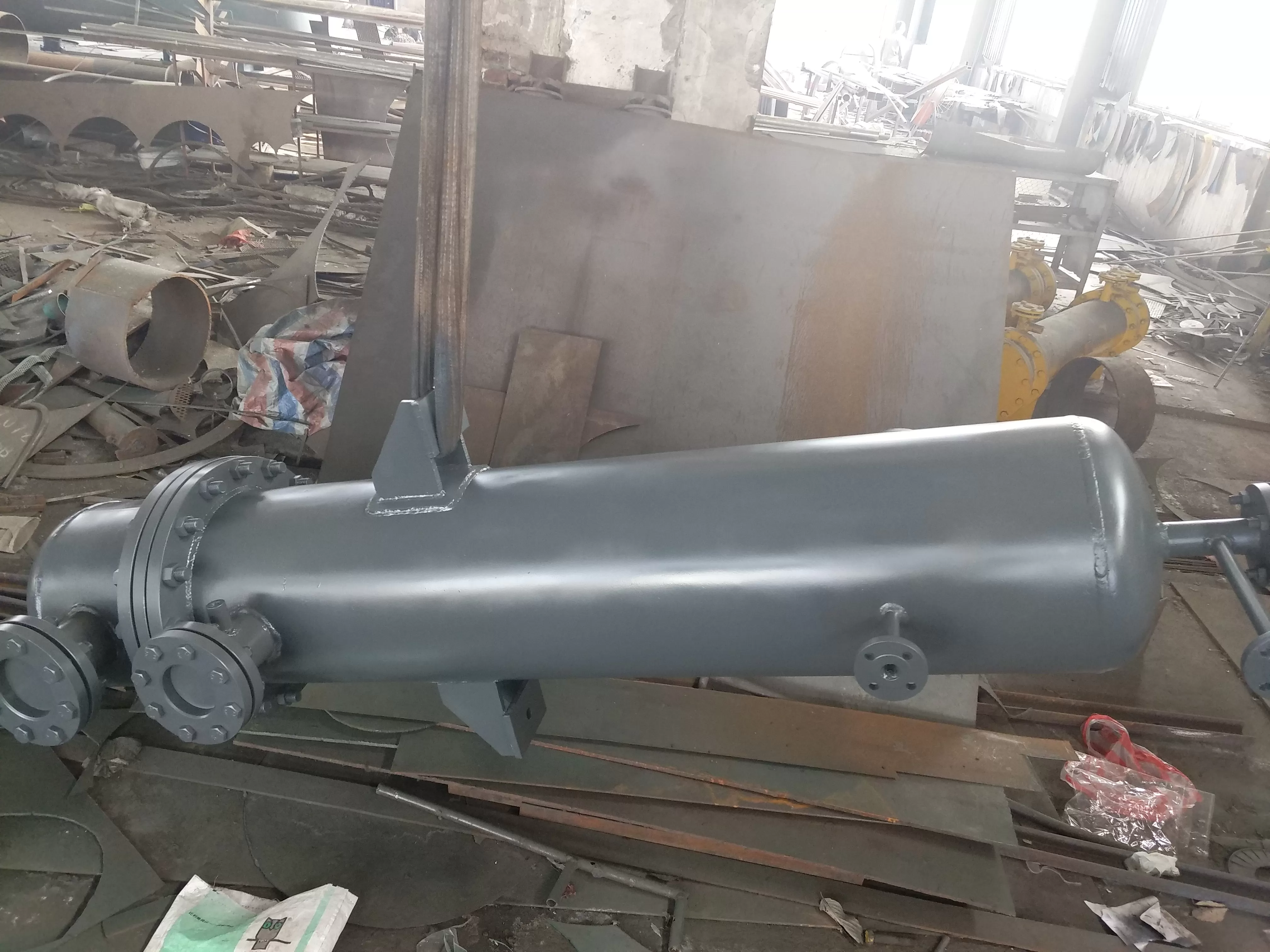
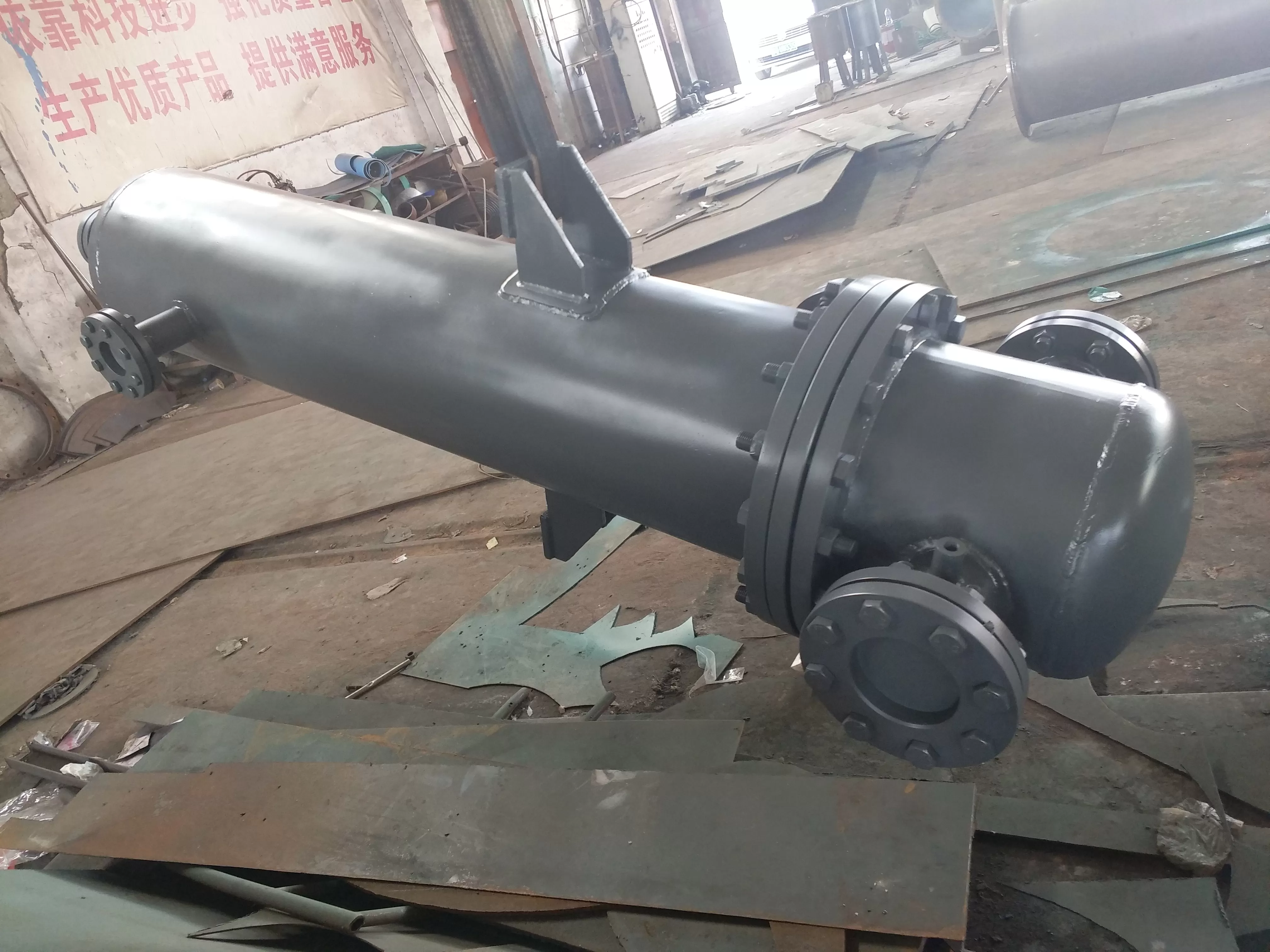
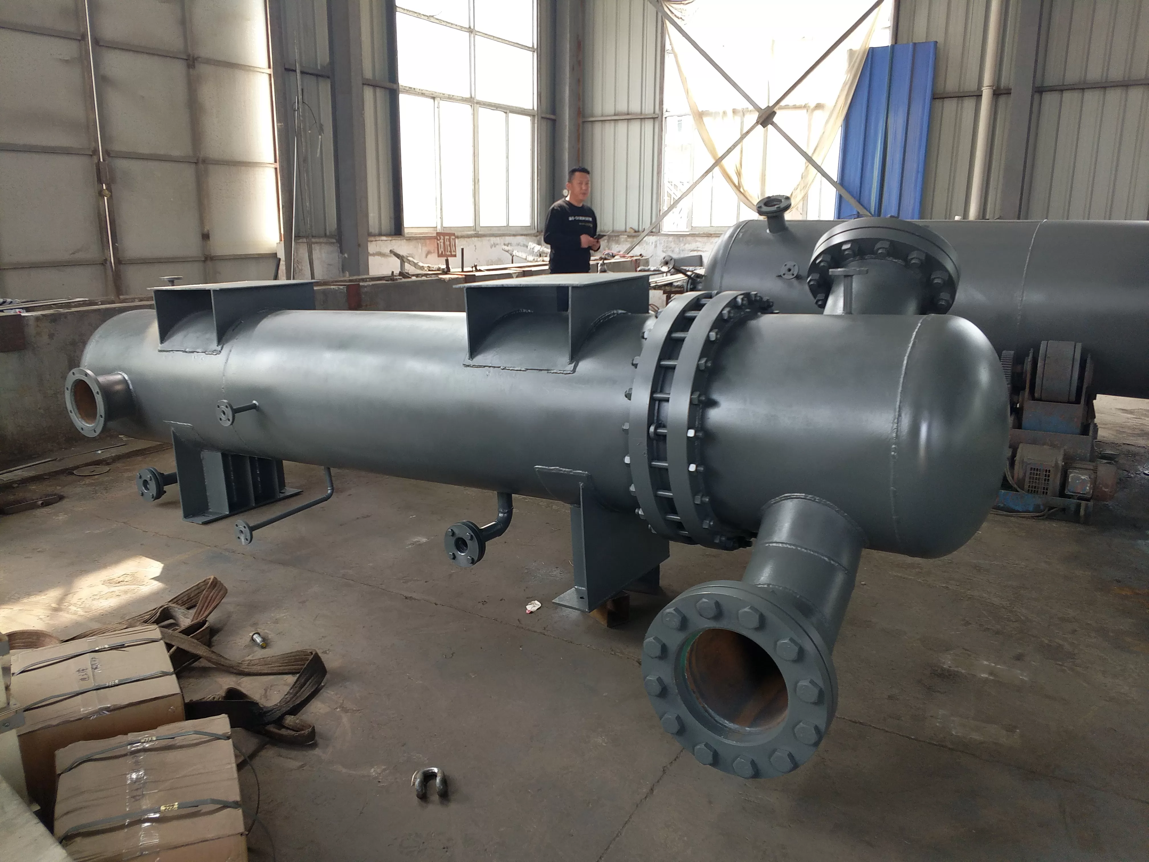
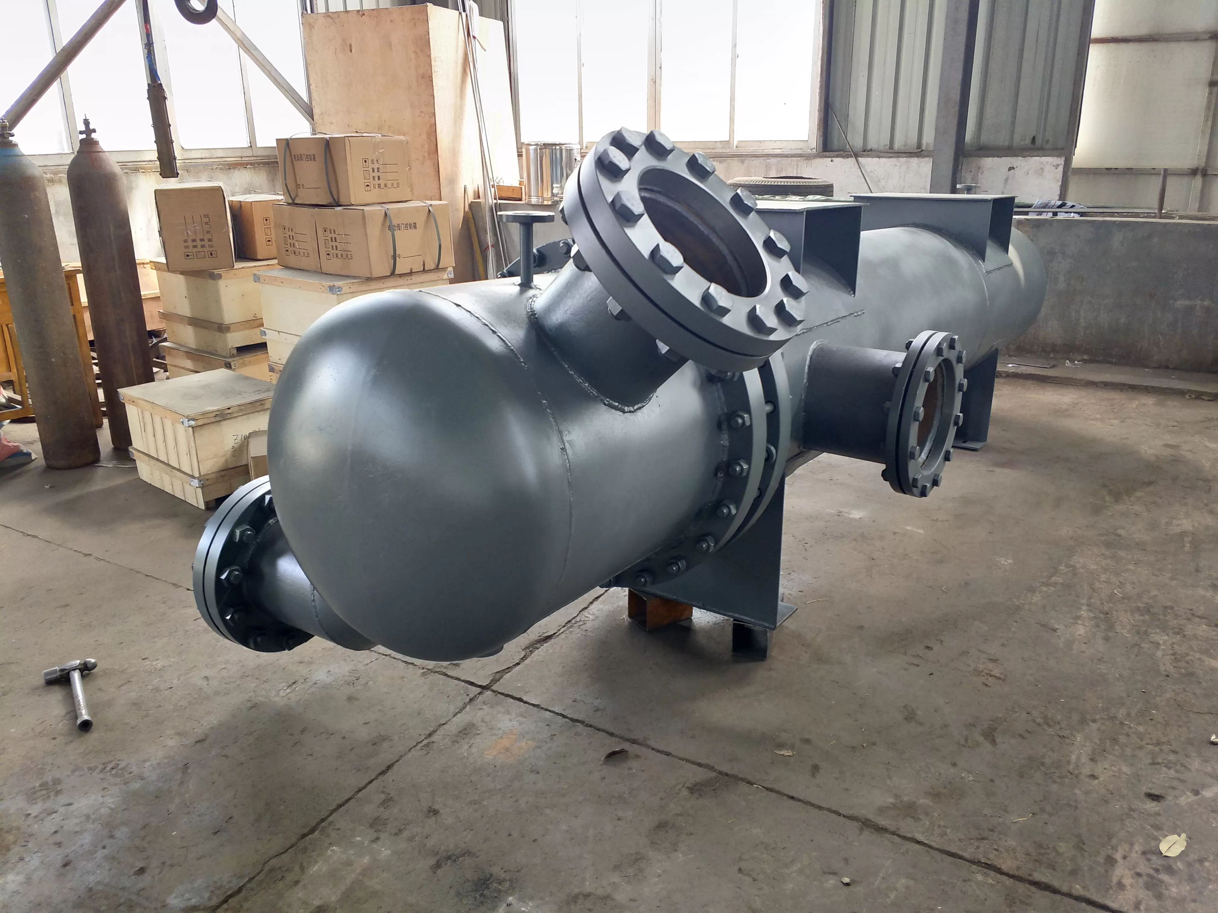
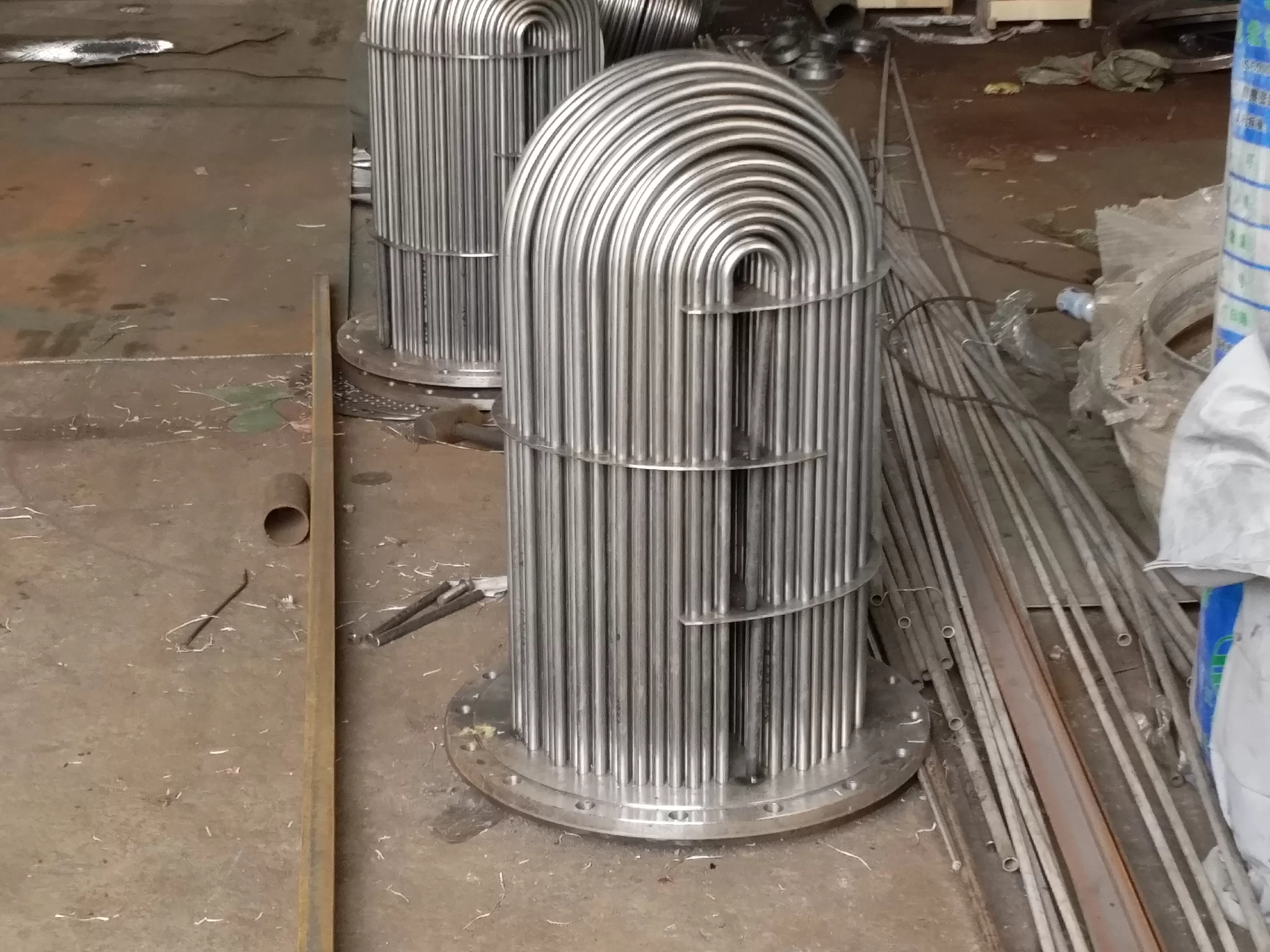
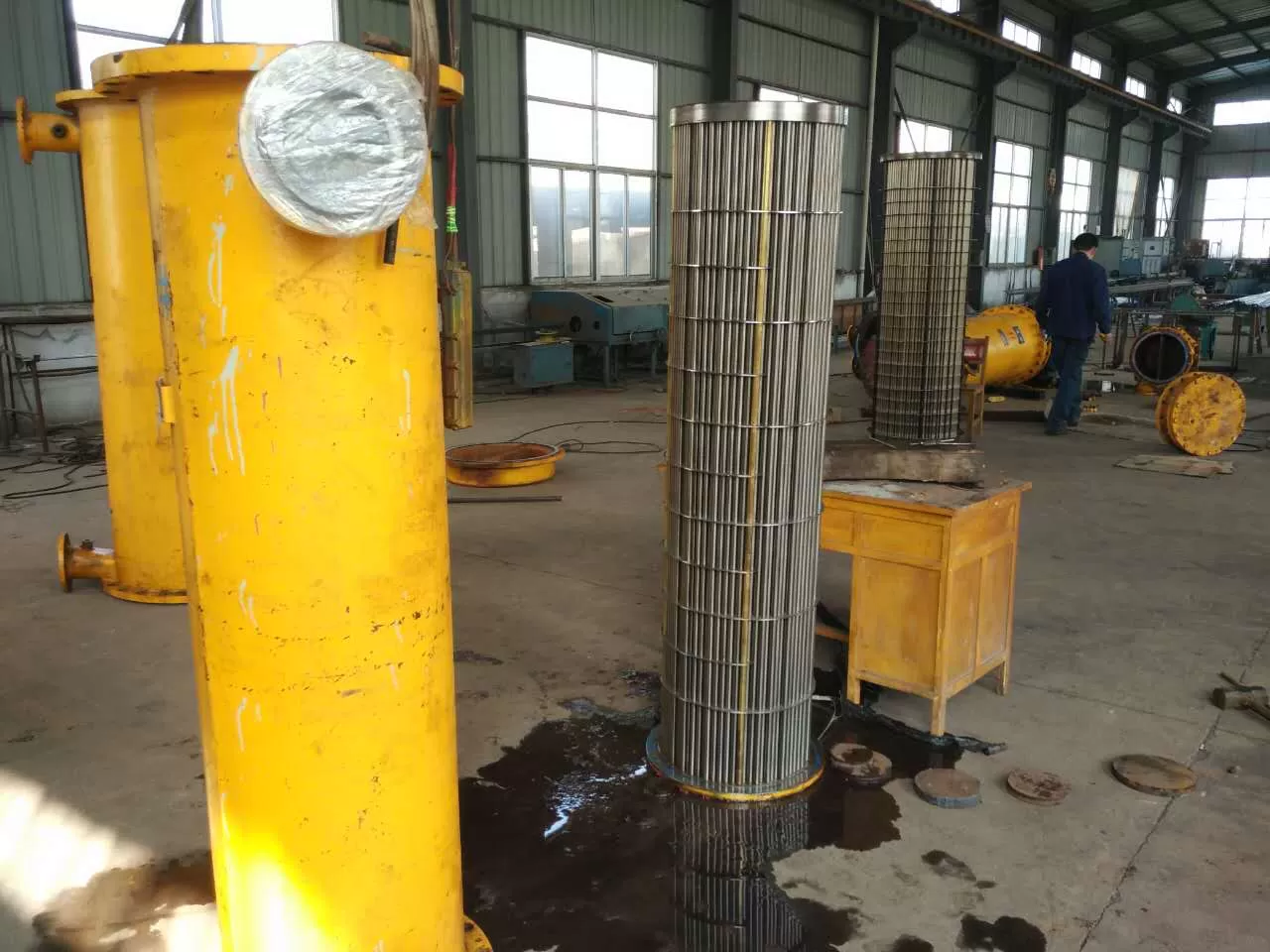
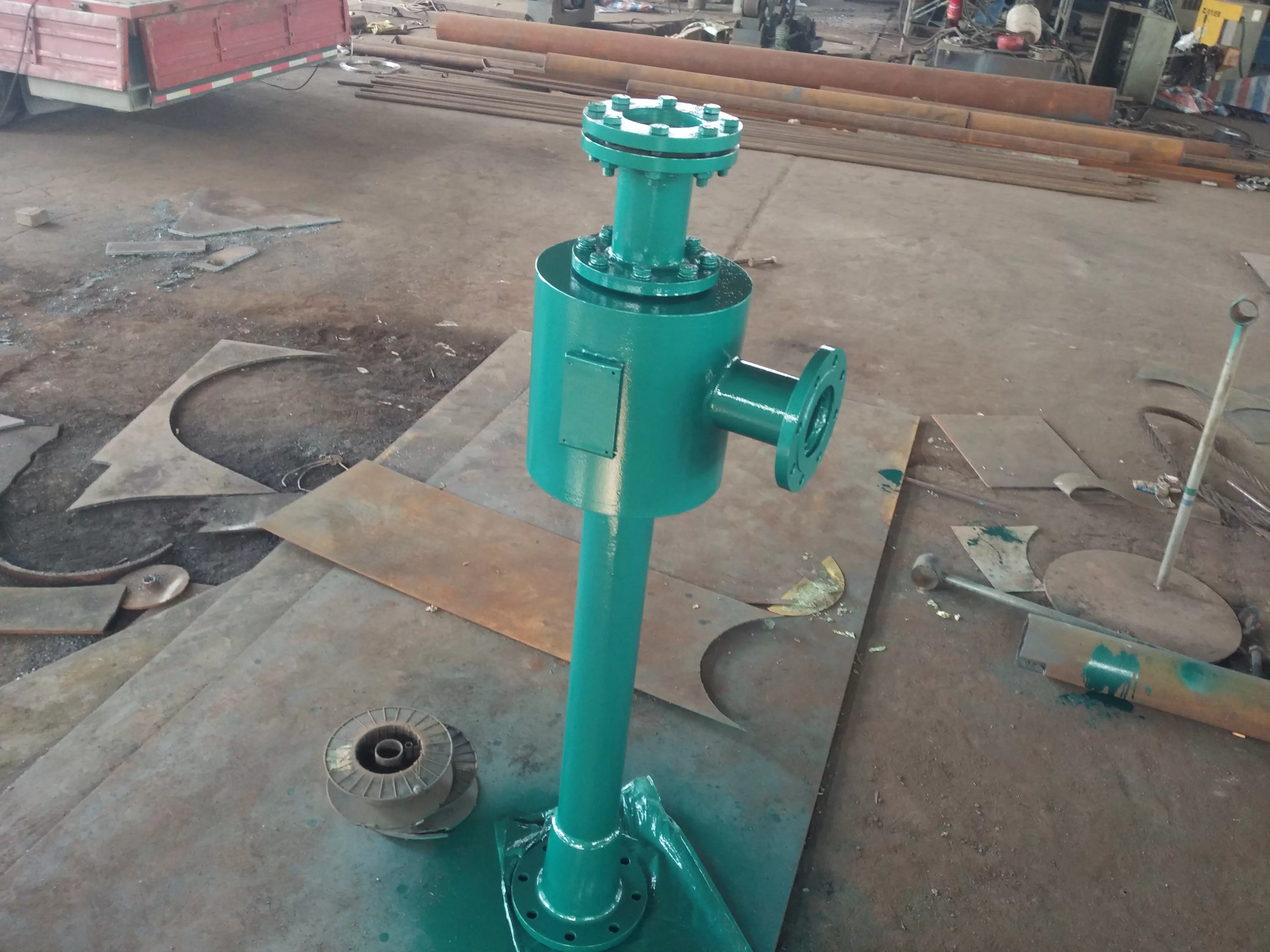
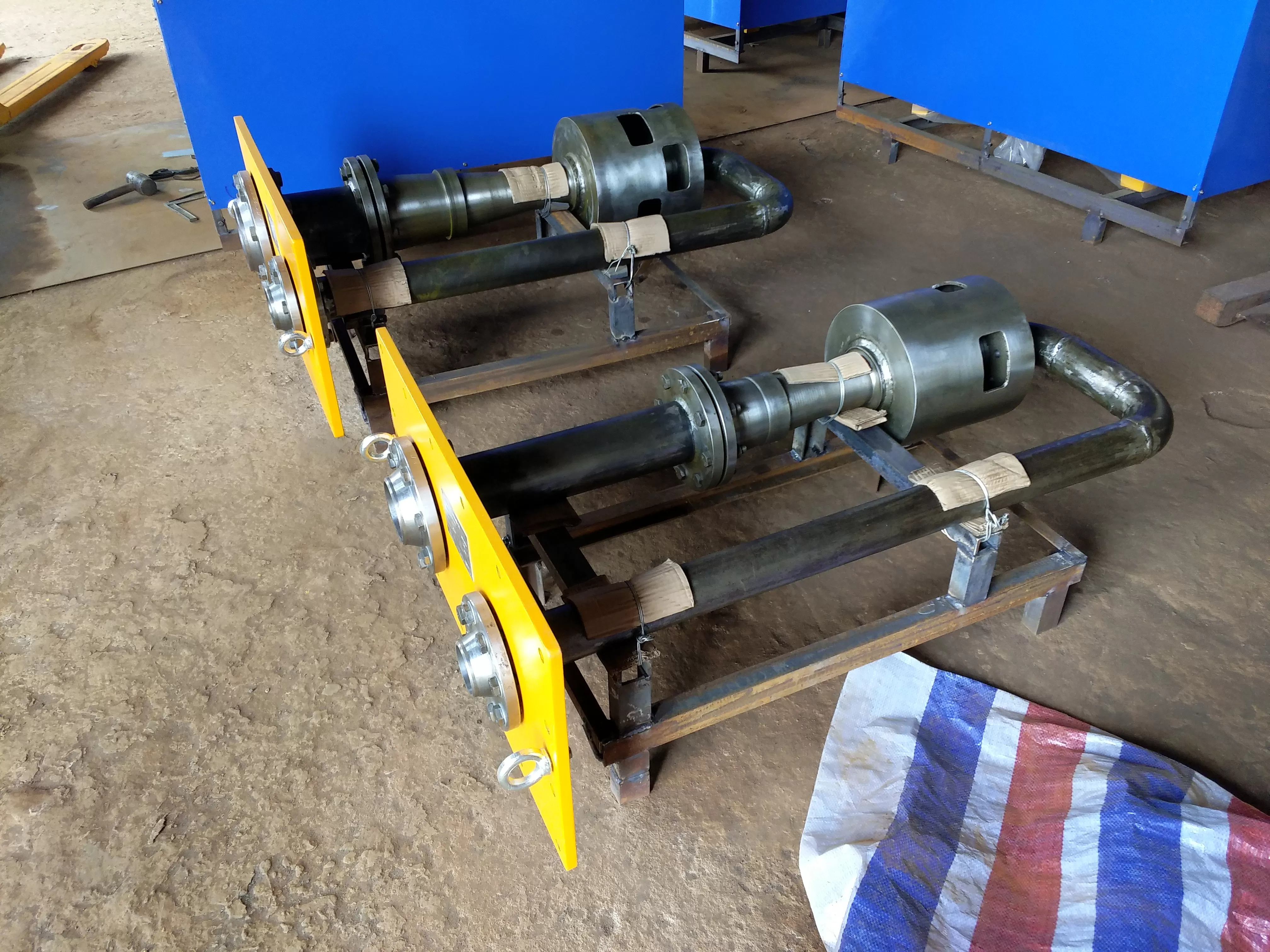
The upper part of the cylinder body of the deaerator energy harvester is equipped with a spray cooling pipe chamber, which is composed of a high-pressure rotary jet injector and a cooling pipe, and its side is connected to a cooling water inlet pipe. Below the spray cooling pipe chamber is the atomization space, and below the atomization space is the heat and mass transfer component. Below the heat and mass transfer component is the steam distributor, which is connected to the exhaust pipe on the side.
This type of exhaust energy harvester is different from the ordinary deaerator residual steam recovery device. It condenses the three heat and mass transfer methods of atomization, water spraying tray, and liquid film into a body, so it has a high efficiency. It not only has a great heat absorption function, but also has strong analytical ability for non condensable gases. The ordinary water spraying and falling film are replaced by strong atomization and falling film, which increases the degree of the liquid film and makes the liquid film strongly entrain a large amount of steam, increasing the heat and mass transfer function.
Introduce the exhaust (steam) of the deaerator into the residual steam recovery tank from the inlet, and combine it with the supplementary water or condensate water introduced from the inlet for mass transfer. Under the action of the internal mass transfer medium, water and steam are fully in contact, and the "inlet" absorbs the water vapor contained in the "inlet" and discharges it into the drainage tank from the bottom outlet of the tank. Non condensable gas is discharged into the atmosphere from the tank outlet. The residual steam of the deaerator passes through the cooler, and then the flow of make-up water is adjusted to regulate the water temperature of the drain tank. The cooling water enters the tower body from the inlet and reaches the upper cooling plate. When the water level exceeds the buffer plate, it flows through the cooling holes to the upper cooling plate and then from the cooling plate to the lower cooling plate. During this process, the cooling steam is heated again, and then flows into the drainage tank from the outlet for recycling.
Economic analysis of the use of waste heat recovery equipment:
Thermal deaerator waste heat recovery device: It is known that 350t of desalinated water is replenished daily, the desalinated water pressure is designed at 0.5Mpa, the exhaust temperature is 110 ℃, the exhaust pressure is 0.02Mpa, and the desalinated water is heated from 20 ℃ to 60 ℃. The calculation results are as follows:
1. Calculation of the recovery of desalinated water by the deaerator waste heat recovery device:
Calculated by the formula: GH=GP (hp2-hp1)/(hH hp2).
Equation - GH - Steam flow rate of injector injection (deaerator exhaust steam flow rate)
GP - Flow rate of working water in the heater (desalination water replenishment flow rate)
Hp2- Enthalpy of desalinated water at 60 ℃
Hp1- Enthalpy of desalinated water at 20 ℃
HH - latent heat of vaporization in deaerator exhaust
GP=(350 × 1000)/(24 × 3600)=4.05kg/s
According to the table, hp2=251.5kJ/kg, hp1=84.3kJ/kg, and hH=2691.3kJ/kg
Substituting into the above equation - results in GH=4.05 × (251.5-84.3) ÷ (2691.3-251.5)
=4.05 × 167.2 ÷ 2439.8
=0.28kg/s
zero point two eight × three thousand and six hundred × 24 ÷ 1000=24t/d
24 tons of desalinated water will be recovered daily.
-The verification calculation of the injector injection coefficient: u=GH/GP=0.28 ÷ 4.05=0.069, when the working water temperature is 20 ℃, the injector large injection coefficient can reach umax=0.2, which can meet the requirements of the working condition.
2. Calculation of coal saving amount for deaerator waste heat recovery:
Recovered thermal energy Q=GH (hH hp2)
=0.28 × (2691.3-251.5)
=0.28 × 2439.8=683.14kJ/s
six hundred and eighty-three point one four × twenty-four × 3600=59023641.6kJ/d
Converted to 6000kar standard coal per kilogram, the daily coal savings for deaerator waste heat recovery are 59023641.6 ÷ (6000) × 4.18)=2353.4kg/d=2.4t/d
The waste heat recovery of the deaerator can save 2.4 tons of standard coal per day.
3. Economic analysis of deaerator waste heat recovery device:
According to the above results, if the deaerator waste heat recovery device operates for 8000 hours per year, it will be calculated at 300 yuan per ton of coal.
Deoxidizer waste heat recovery - annual coal saving 2.4 × 8000 ÷ 24=800 tons
Deaerator waste heat recovery - annual cost savings of 800 × 300=240000 yuan=240000 yuan
Deaerator waste heat recovery - annual recovery of desalinated water 24 × 8000 ÷ 24=8000 tons
5��、 Will the use of a deaerator waste heat recovery device affect the deaeration results
Under the same operating conditions of the deaerator and with a sample of exhaust valve opening, the specific analysis is as follows:
Set the exhaust volume to Q gas, the internal pressure of the deaerator to P, and the atmospheric pressure to P0. In Figure 2-, the internal pressure of the deaerator is set to P, the internal pressure of the combined heater is Ph, the exhaust volume of the deaerator is Qh, the water replenishment dissolved oxygen is Q oxygen, and for the gas water separation tank, the automatic exhaust valve exhaust volume is Q gas'.
In the system shown in Figure 2, Ph is the saturation pressure for water replenishment.
Due to PhP-P0
So Qh>Q gas
△ Q gas=Qh Q gas, Q oxygen=Qh Q gas'
If Q Qi=Q Qi '
Then △ Q gas=Q oxygen
This equation is the criterion for determining whether the waste heat recovery device of the thermal deaerator affects the deaeration result.
When Δ Q gas ≥ Q oxygen, the waste heat recovery device of the thermal deaerator will not affect the deaeration result;
When Δ Q gasQ oxygen, which will not affect the deoxygenation effect.
When the exhaust valve is opened appropriately, the exhaust volume will also increase. As the exhaust is recovered by the injection type combined heater, it will not have a negative impact on the economy.
Deaerator waste heat recovery device technology -:
(1) High heat exchange rate, sufficient heat and mass transfer, with a recovery rate of over 99%;
(2) Design - outstanding, structure - simple, low failure rate;
(3) Stable operation, safe and reliable, and easy recycling of cooling water;
(4) Non condensable gases are discharged into the atmosphere, reducing pipeline oxygen corrosion and prolonging the use of equipment pipelines;
(5) Eliminate noise, replace the original deaerator exhaust steam eliminator, and beautify the environment;
Deaerator waste heat recovery device -:
(1) Recovering low-pressure or low-pressure exhaust steam heat energy and condensate water; Simultaneously discharge various gases such as exhaust steam and heating water;
(2) Automatic liquid level adjustment system for small volume and large flow separation tanks;
(3) Compact structure, small footprint, and convenient access to the system.
(4) The use of suction injection steam (gas) method does not affect the positive emission of the process.
(5) Designed as a "self rinsing" structure to minimize the formation of scale.
(6) - The pump supplies high-pressure water pipelines without consuming additional factory electricity.
(7) The recovery device is located on the deaeration platform, and the pipeline is between the high and low desalination water pipes, with a close distance and low construction cost.
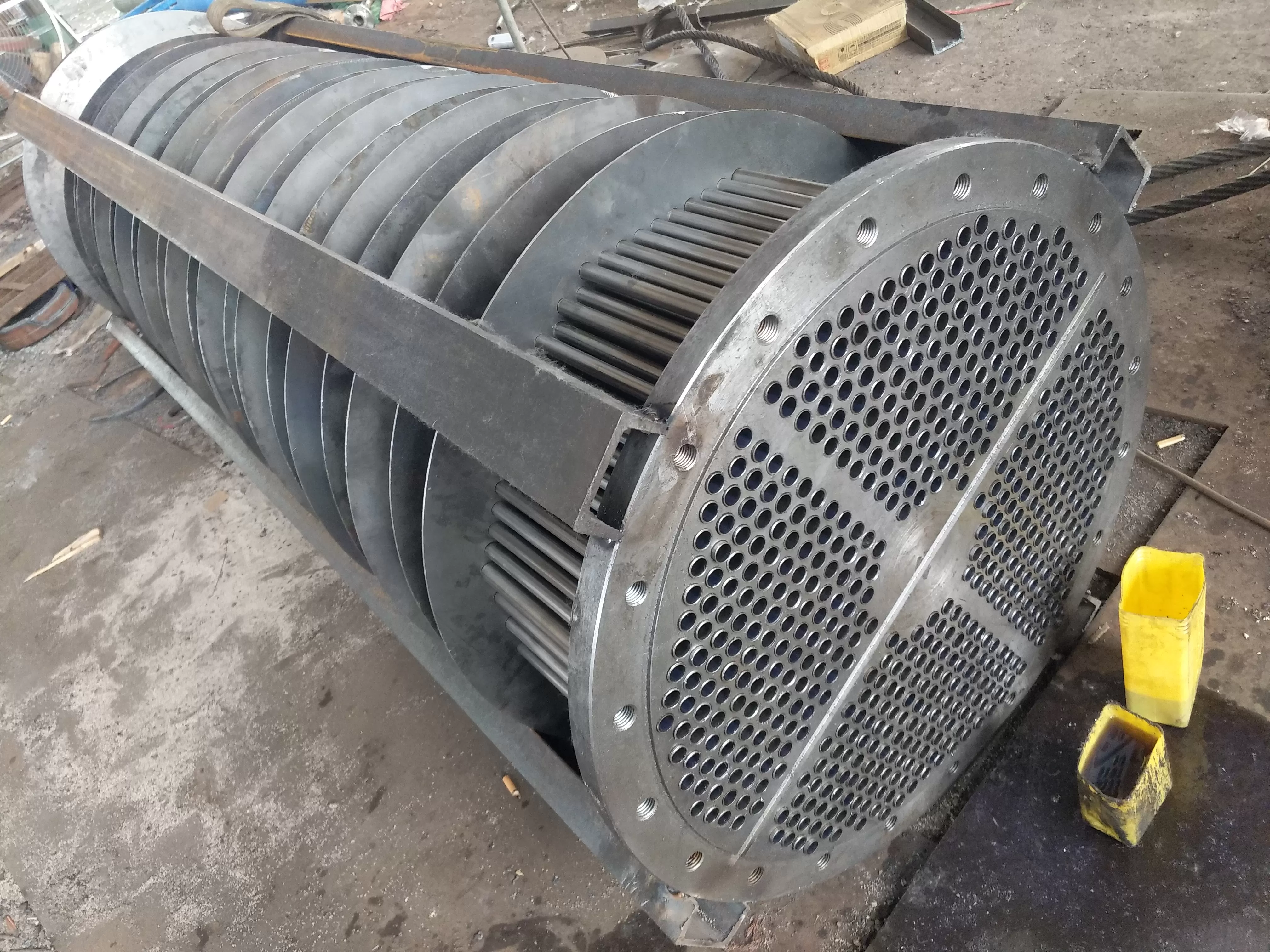
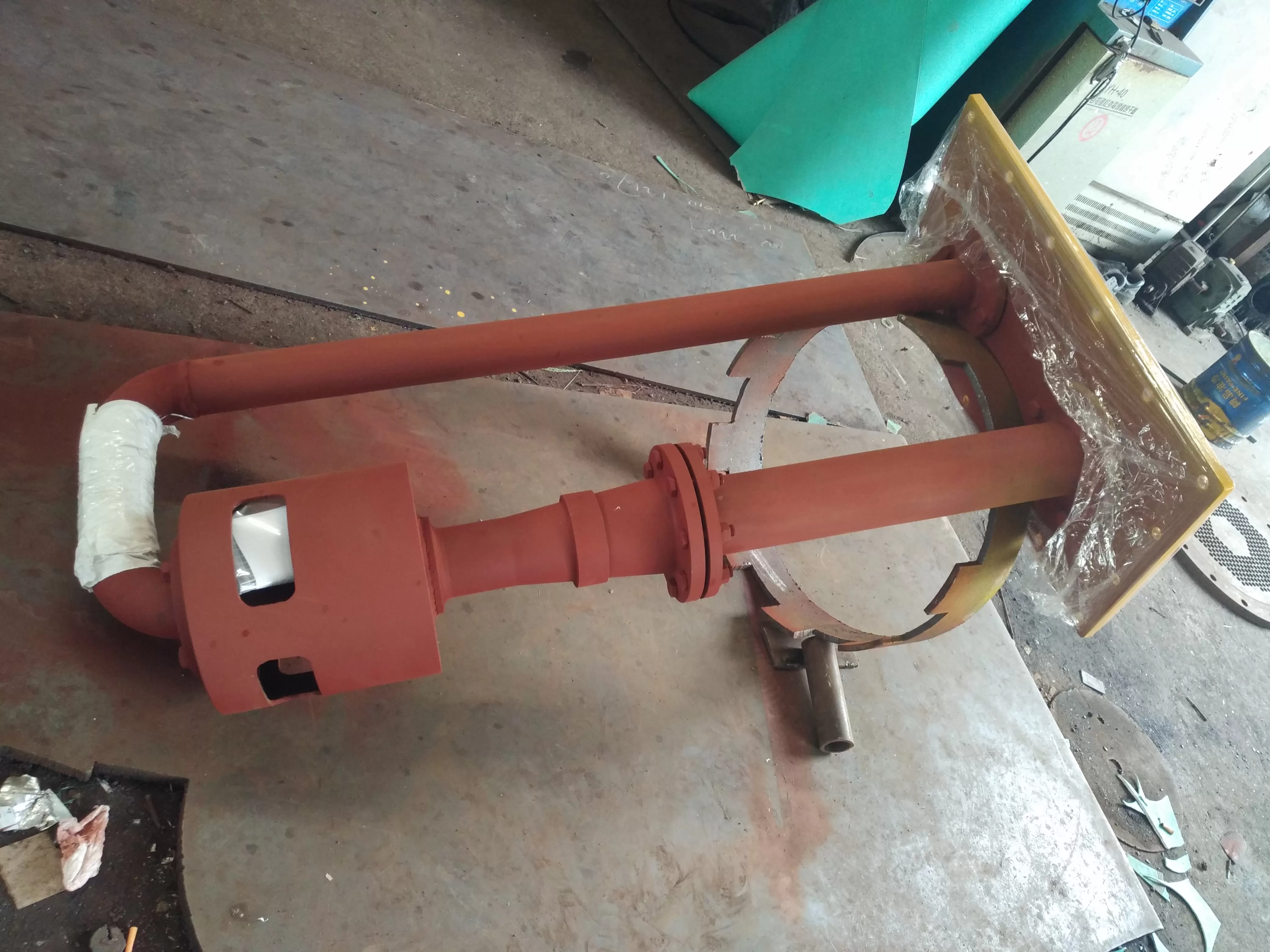
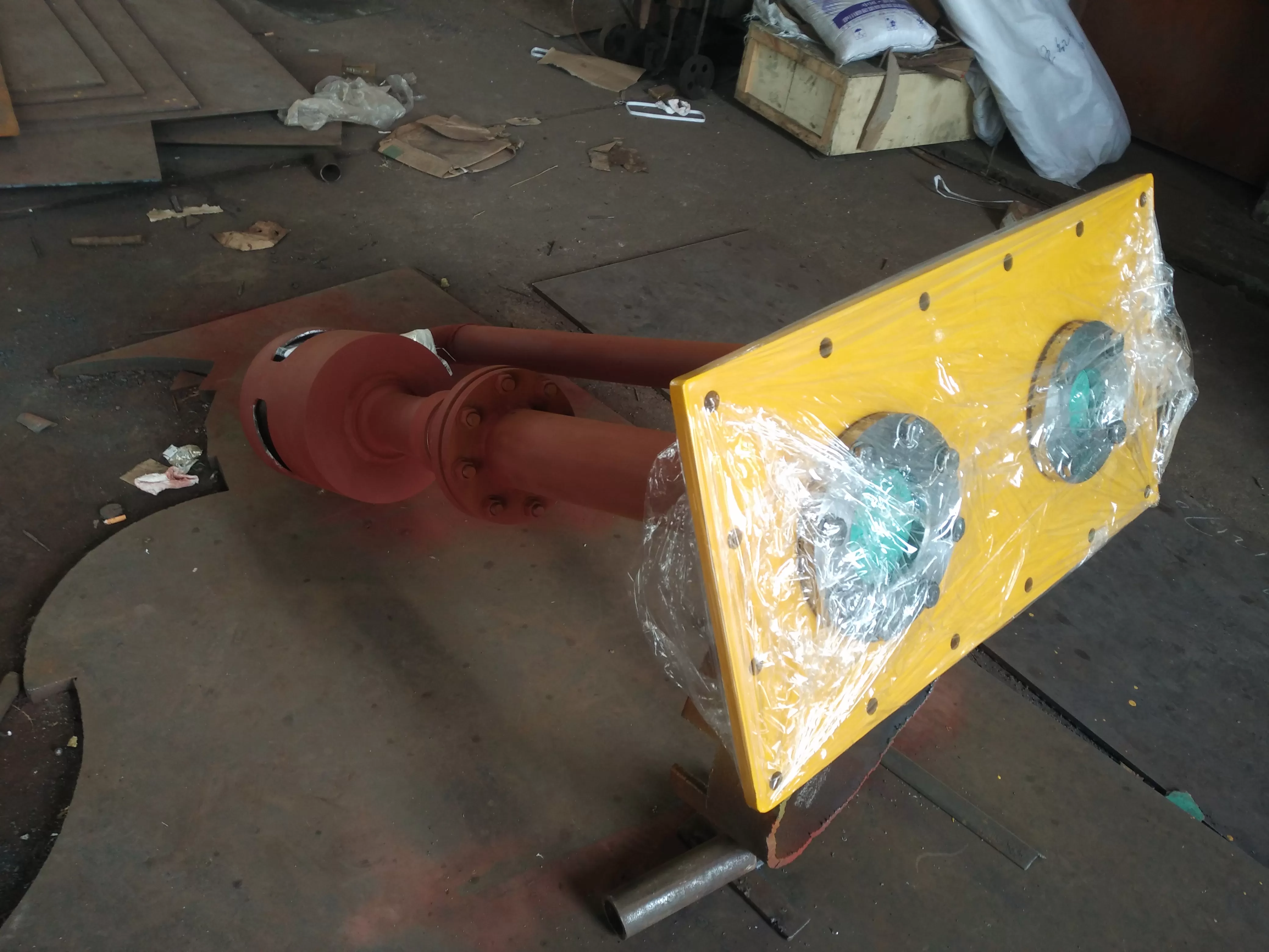
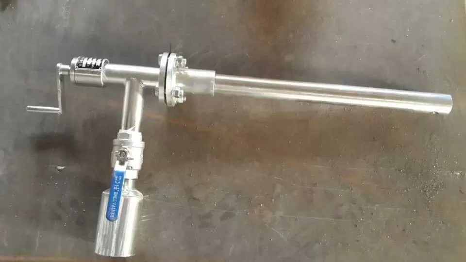
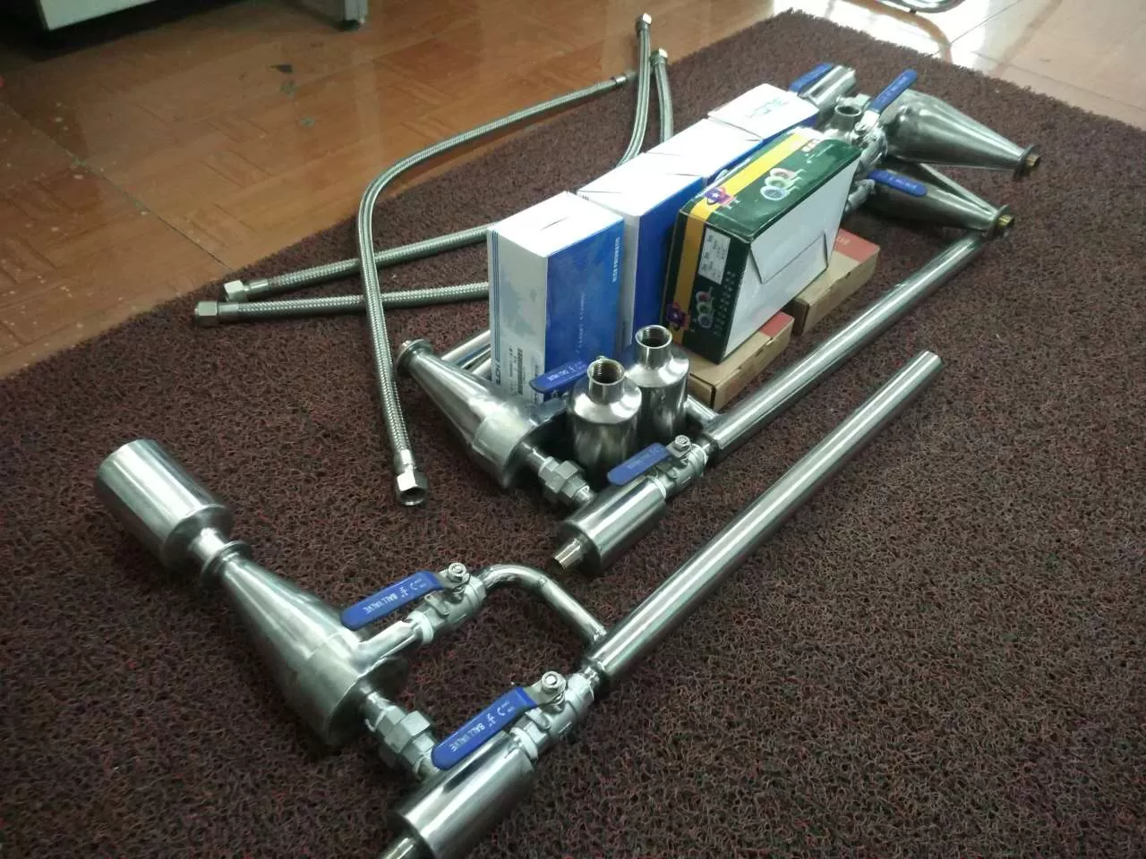
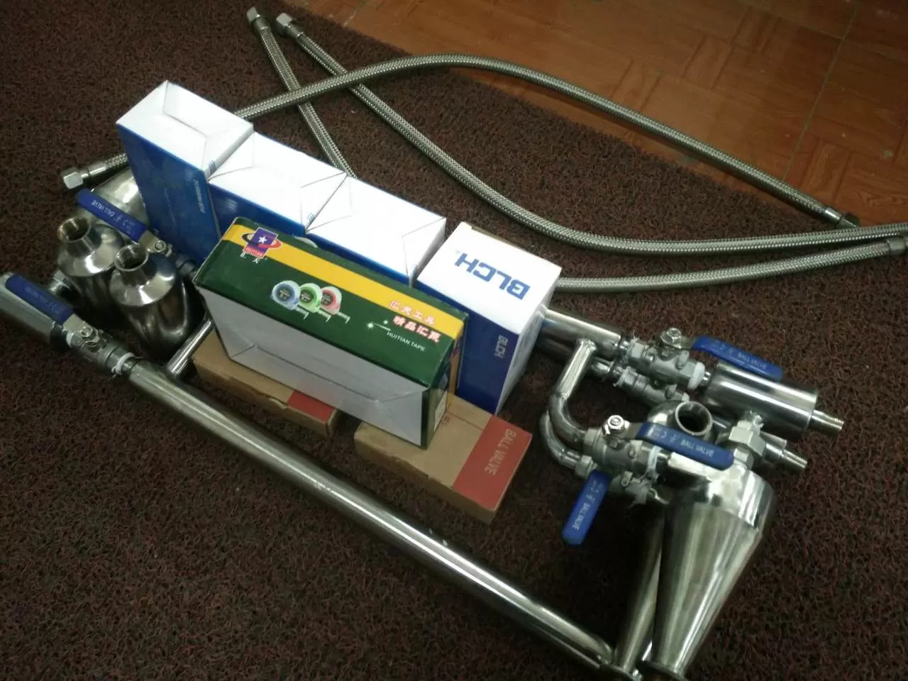
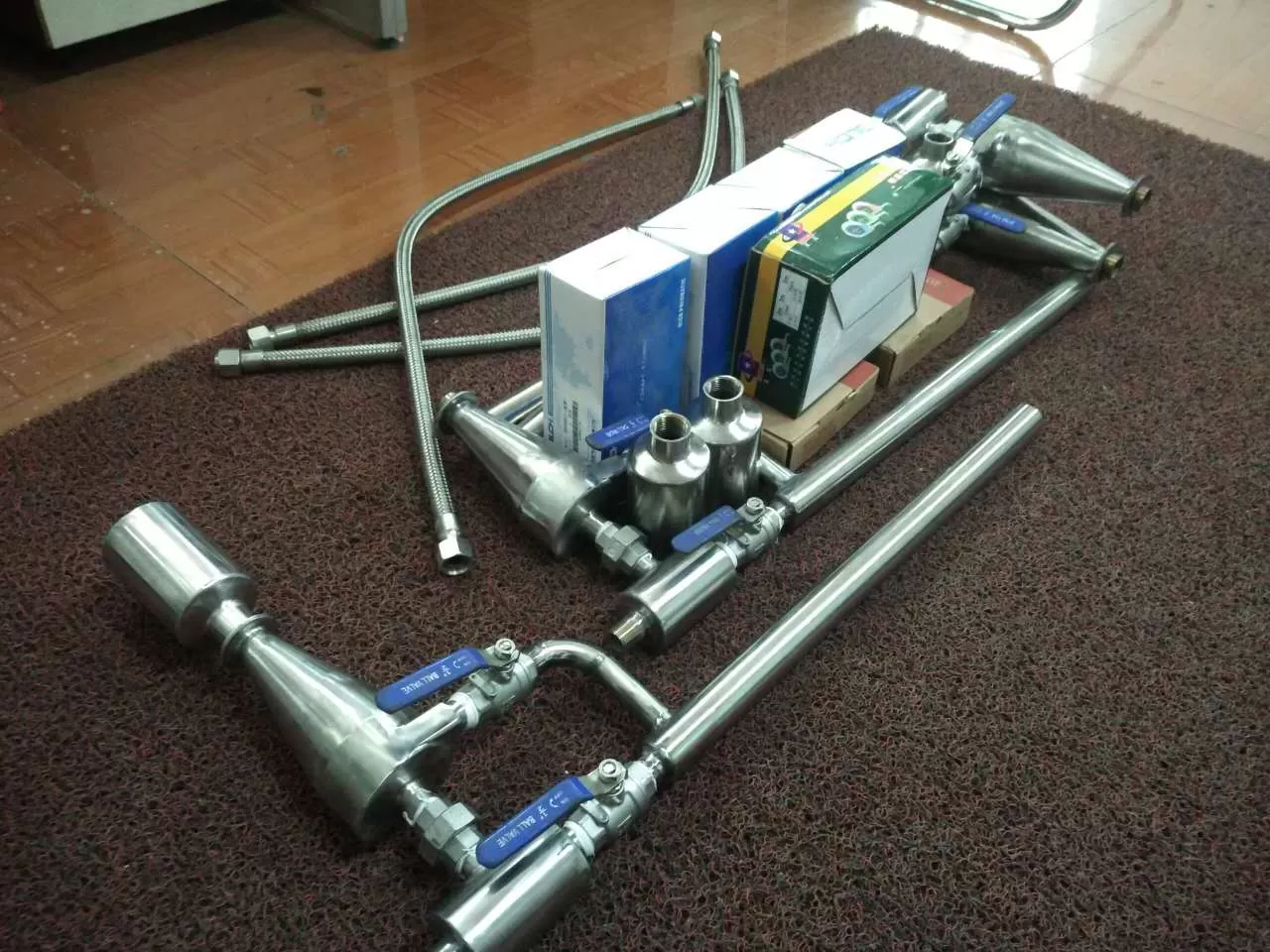
Jet combined heater as the recovery body of the deaerator waste heat recovery device
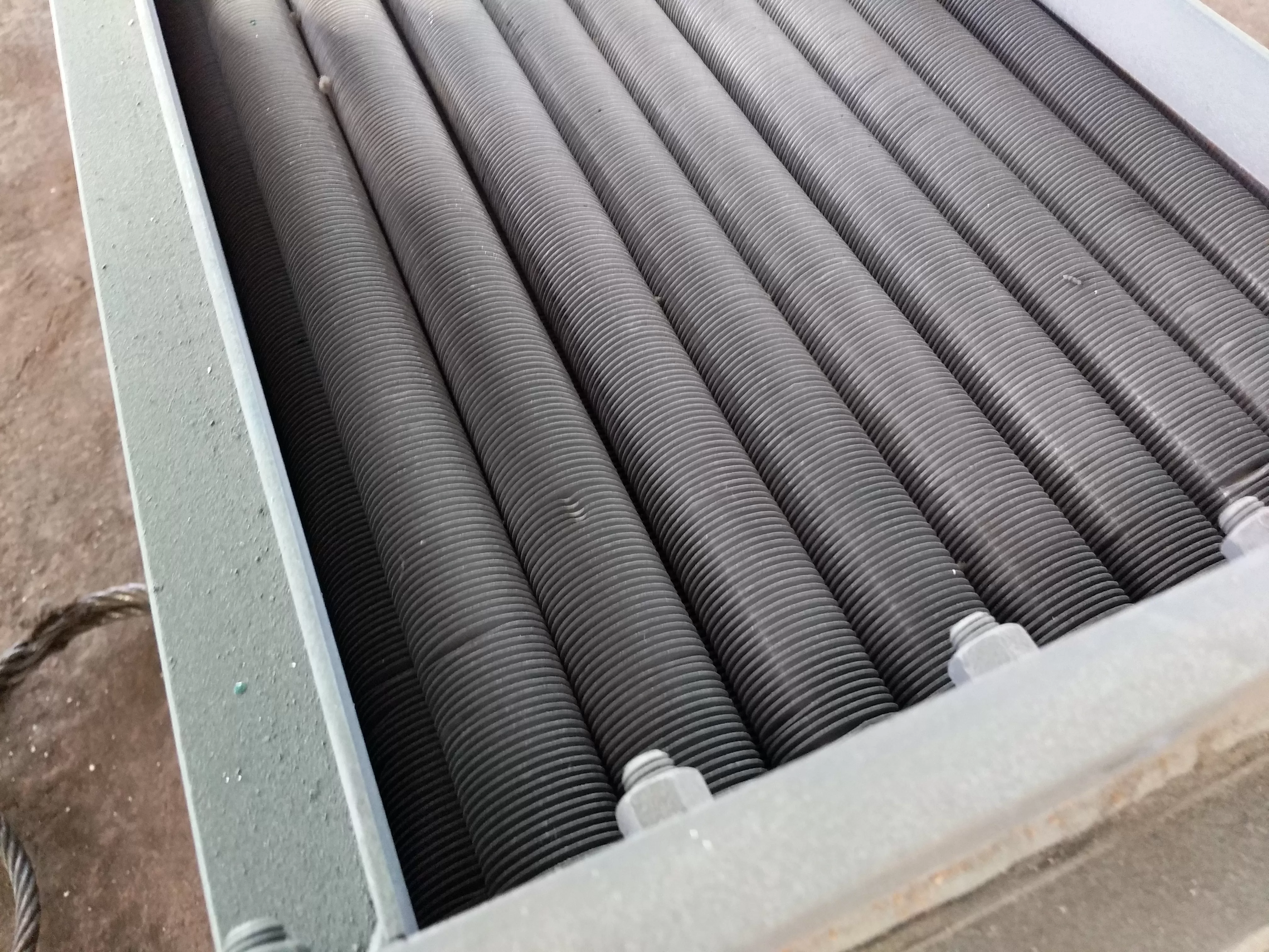
The deaerator waste heat recovery jet combined heater consists of a shell, a nozzle (single or orifice), a combined pipe, and other components. When the heated liquid passes through the nozzle, a certain low pressure is formed at its throat (or false throat), which sucks in the exhaust steam and combines with the heated liquid through the combined pipe to achieve the purpose of heating. The liquid heated to the required temperature flows out from the outlet of the heater.
There are two types of jet combined heaters: liquid jet and steam jet. When the steam pressure is stable and the thermal load changes little, steam jet can be used. Its function is to utilize the available energy of steam, reducing the energy consumption of the driving pump (circulation pump), that is, electricity consumption. In general, the jet type combined heater can meet the user's usage requirements.
Overview of thermal deaerator waste heat recovery device:
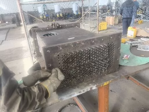
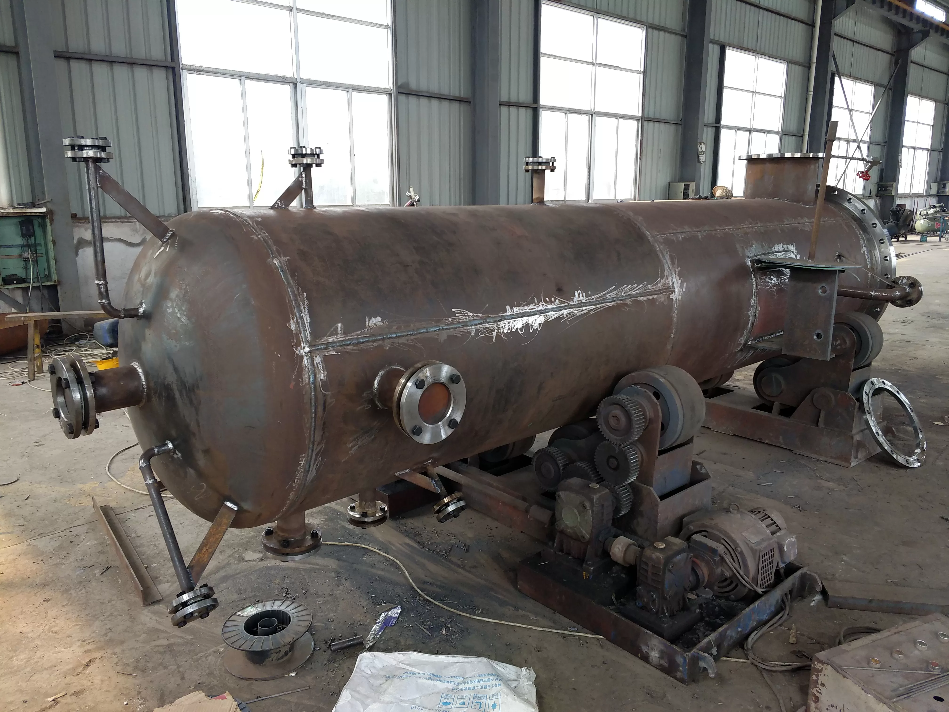
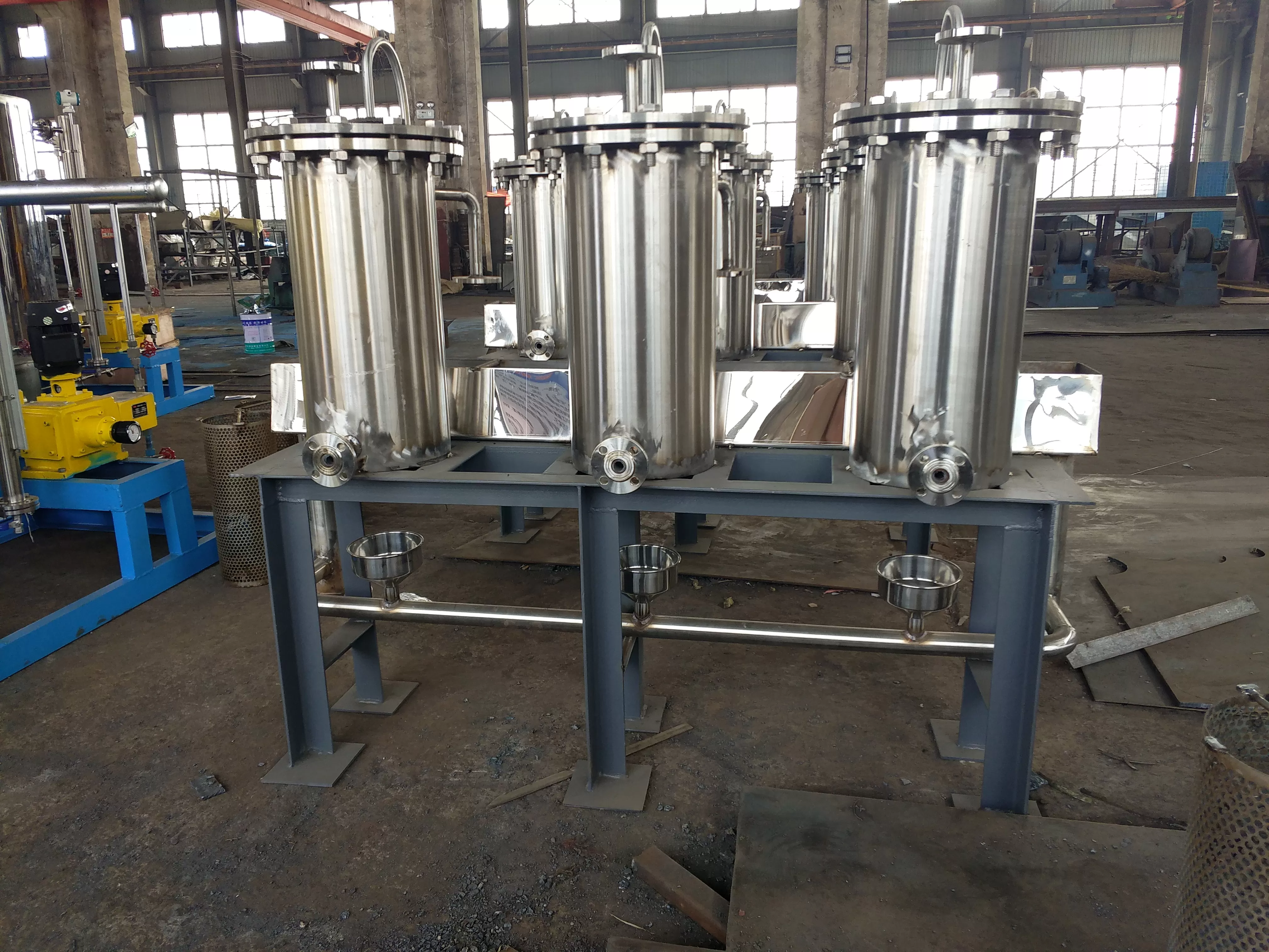
The deaerator waste heat recovery device is an integrated device consisting of three units (modules): a suction exhaust steam heating device, a gas-liquid separation tank, and gas discharge, hot water pressure recovery and lifting, as well as random liquid level control and thermal energy recovery metering instruments. It is connected to the exhaust steam recovery system through three interfaces.
1. Proportional superposition regulation technology with high flow rate and small volume
The tank body of its gas-liquid separation tank is compact, with a storage capacity of only a fraction of the standard design, and the level fluctuation control is very high- Fully automatic and stable operation with personnel on duty. This allows the deaerator waste heat recovery device to be installed in narrow spaces, even on the deaerator platform, resulting in high heat recovery rate and low heat loss.
2. Power head for stable operation under wide load
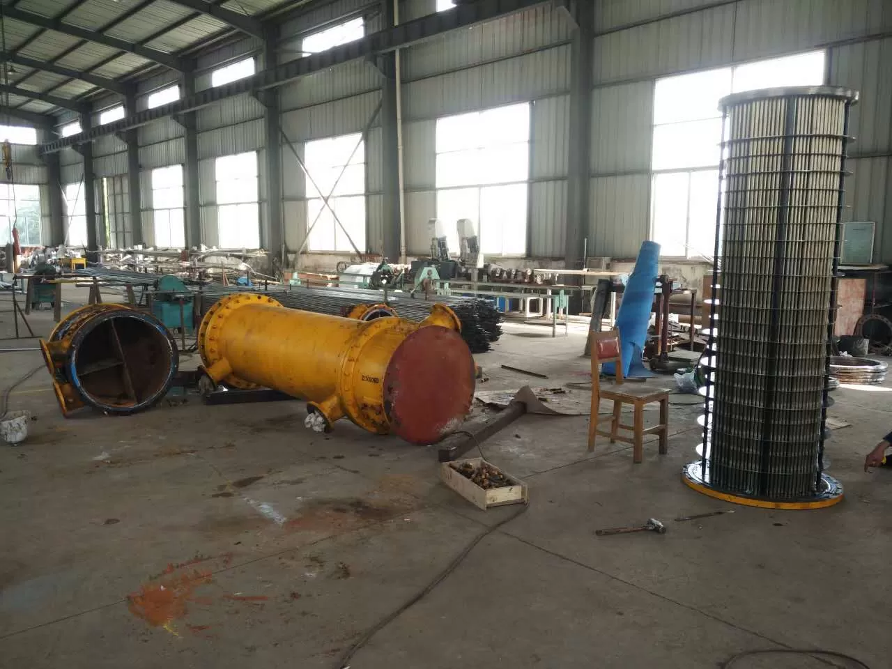
Process flow of deaerator and energy collector:
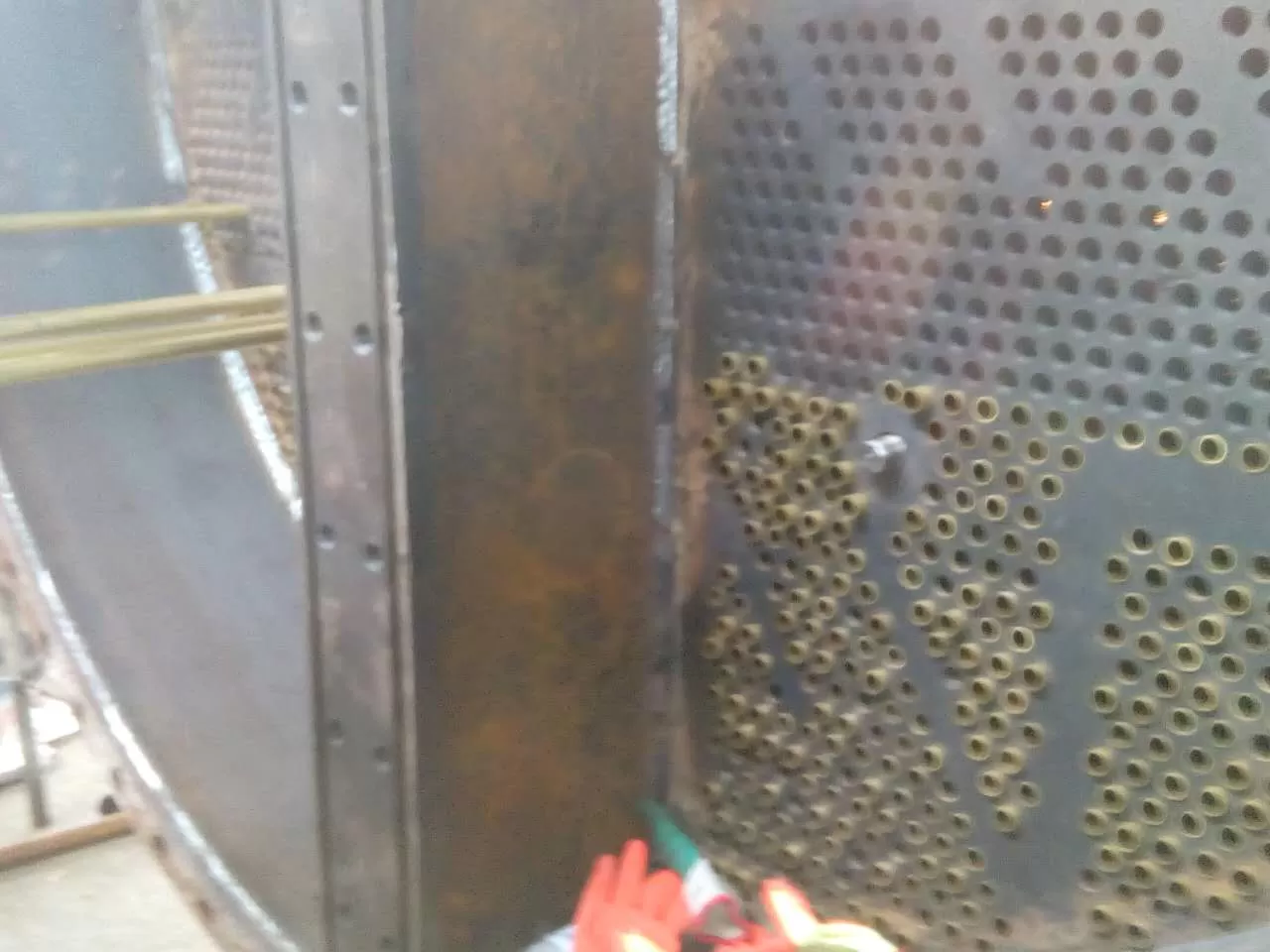
The cooling water is introduced from the inlet pipe of the deaerator steam collector through the desalination water main pipe, and the deaerator steam is discharged from the deaerator exhaust valve and connected to the energy collector. After sufficient mass and heat transfer inside the equipment, non condensable gas is discharged from the upper exhaust gas outlet. The condensed water flows downward along with the sprayed atomized liquid film, flows out from the outlet, and enters the drainage tank.
Specification, model and technical parameters of waste heat recovery device:
型號 | H | D1 | D2 | D3 | D4 | D5 | D6 | DN |
CYH-75 | 1800 | 65 | 65 | 40 | 40 | 40 | 40 | 350 |
CYH-100 | 1950 | 80 | 80 | 50 | 50 | 40 | 40 | 400 |
CYH-150 | 2200 | 100 | 100 | 65 | 50 | 65 | 40 | 450 |
CYH-220 | 2300 | 125 | 125 | 80 | 65 | 80 | 50 | 500 |
CYH-300 | 2400 | 125 | 125 | 100 | 65 | 100 | 50 | 550 |
CYH-420 | 2500 | 150 | 150 | 100 | 80 | 100 | 65 | 600 |
CYH-680 | 2600 | 150 | 150 | 100 | 80 | 100 | 65 | 650 |
CYH-1100 | 2800 | 200 | 200 | 125 | 100 | 125 | 80 | 700 |